Home
- Download EvvGC-PLUS release package.
- Unpack using open source 7zip software.
- Flash the firmware using microcontroller's build-in bootloader and Flash Loader Demonstrator Tool (STSW-MCU005) from STMicroelectronics. I am not going to describe flashing of the STM32F103 microcontroller in details. The detailed procedure can be found elsewhere.
- Connect the EvvGC board to the PC via USB cable. If your board is EvvGC v1.2 then connect LiPo battery to provide power to the board. If the board is connected for the first time the Virtual COM Port (VCP) drivers (STSW-STM32102) from STMicroelectronics should be installed.
- Run EvvGC-PLUS Configurator GUI Tool.
- Select the VCP of your EvvGC board.
- Click Connect button.
- Click Read button.
- By default all outputs and inputs are disabled, stabilization is disabled as well.
The current version of EvvGC-PLUS firmware does not have a complete recovery procedure from I2C errors. If serious I2C error occurs, the onboard system is partially halted:
a) data from the sensor are not updated (straight lines) b) settings cannot be saved.
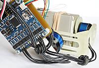
The user must ensure 100% I2C error free design of the gimbal. It is highly recommend to add ferrite rings on motor wires (2-3 windings are enough) and to use twisted I2C connection cable shorter than 30 cm. Keep I2C cable away from battery and motor wires because motors are major source of I2C errors.
Dead-time values are very important for EvvGC board. The major drawback of EvvGC board design is its very weak power transistor driving capabilities (that’s why I do not use EvvGC board anymore). Huge dead-time values must be applied to prevent power transistors from overheating and self-destruction. Huge dead-time values also significantly reduce resolution of the motor drivers. Some positions cannot be reached by the motor because they are prohibited by dead-time leading to gimbal instabilities and premature oscillations.
To set up dead-time motors must be connected to the board.
It is recommended to select the smallest dead-time value possible, because dead-time value has huge influence on motor driver resolution.
It is also recommended to use 2S batteries to power the board or to use 3S-4S batteries in conjunction with adjustable step-down voltage regulator tuned to 7-8V (or even lower) output voltage. It is highly recommended to use lower voltage but higher power values for the motors, because at high power, resolution of motor driver is higher and at low voltage, efficiency of motor driver is higher.
For example: it is MUCH better to power the board using 5-6V voltage and set 80% power for the motor than to use 12V voltage and set 20% power for the motor.
IMPORTANT! Power of the motors should be sufficient to hold the camera. It is bad when when power is too high. To achieve stable and vibration free performance of the gimbal at high power, PID values should be decreased. Lower PID values leads to lower stabilization speed and accuracy.
Procedure:
- Select Outputs tab.
- Select dead-time value smaller than 5000 ns (5000 ns is almost unusable) (for example 4000 ns).
- Click Save button.
- Power cycle the board. N O T E : one MUST power cycle the board because EvvGC-PLUS firmware uses hardware configuration-lock scheme to increase reliability of the motor drivers and to prevent incorrect reconfiguration of the drivers during runtime if something wrong happens, that’s why new dead-time values will not take effect until board is restarted.
- Connect to the board again.
- Set motor power to none zero value for each of the channels (for example 20%).
- Enable channels by selecting an appropriate Command value (for example Roll to Roll, Pitch to Pitch and Yaw to Yaw).
- Click Set or Save button.
- Observe if power transistors (FETs) are getting hot (70°C or more).
- If FETs are not hot then you can decrease dead-time values even more or increase power of the motor and repeat dead-time tuning procedure starting from step 3.
To setup direction of the motors all values in Stabilization tab must be set to ZERO.
Motors must have power greater than ZERO and output channels must be enabled by selecting an appropriate Command value in Outputs tab.
Orientation of the sensor board must be correct.
All inputs must be disabled.
Follow mode must be disabled.
Attitude of the camera itself has to be none flat/horizontal.
- Select Stabilization tab.
- Set value of the Pitch I to ONE (1). N O T E : this is not PID tunning, I = 1 is way too low for proper PID values.
- Because attitude of the camera is not horizontal, the gimbal should start to stabilize the camera by slowly rotating the pitch motor towards the horizontal position.
- If the motor rotates the camera towards even more none horizontal position it means that the direction of the pitch motor must be reversed by clicking Reverse checkbox in Outputs tab.
The same procedure is valid for Roll and Yaw axes.
The most important values are I and D. It is recommended to start from D.
- D value (acceleration of the motor) is responsible for oscillations dampening. Range of proper D values is roughly from 60 to 120.
- I value is responsible for the speed at which actuator reaches its desired position or offset. Range of proper I values is roughly from 40 to 80 (but can be higher).
- P values (rotation speed of the motor) can be equal to I values.
There are two types of inputs:
- analog inputs and
- PWM (pulse width modulation) inputs.
The full input range of analog inputs is from 0 (0V) to 4095 (3.3V) (12 bits).
The full input range of PWM inputs is usually from 1000 to 2000, but it depends on RC transmitter-receiver combo used.
Analog inputs are good for various analog joysticks and/or potentiometers.
To control attitude of the camera using a joystick:
- Connect the output of the joystick to AUX1 or AUX2 channel of the EvvGC board.
- Select AUX1 or AUX2 channel as input source.
- Set Min value of the channel to 0.
- Set Max value of the channel to 4095.
- Set Neutral value of the channel to 2047.
- Click Save button.
- You have to adjust Neutral value of the channel later on because actual neutral values are usually a little bit different due to poor manufacturing quality of the joystick.
- Try to control the attitude of the camera.
- To reverse the direction of camera movements user have to swap Min and Max values of the channel.
PWM inputs are used to connect RC receiver.
Tuning procedure for PWM channels is the same.
Signals from input channels effect orientation of the camera only if Angle or Speed mode is selected.
Follow mode is not effected by signals from input channels.
There are three input modes:
In angle mode attitude of the camera is controlled by signals from input channels. Attitude of the camera is proportional to the value of the input signal and is constrained by Min Angle, Max Angle and Speed values.
In speed mode attitude of the camera is also controlled by signals from input channels.
The attitude of the camera is not proportional to the value of the input signal. In speed mode the rotation speed of the camera is proportional to the value of the input signal and is constrained by Speed value only.
In follow mode attitude of the camera is controlled by moving the gimbal frame itself (signals from input channels are ignored). Movements of the camera are constrained by Speed value only. Follow mode is also effected by Offset values. Offset values represent the misalignment between mechanical and electrical coordinate system of the motor during motor manufacturing and/or gimbal design process.
Sensor board must in flat/horizontal position.
Procedure:
- Click Accel Calibrate button.
- Wait until LED on the EvvGC board stops flashing fast.
- Click Save button.
For linux, it's straightforward, if you have all the dependencies.
For windows, here are the original instructions:
- Download 32-bit Qt 5.5.0 Community Open Source for Windows with MinGW 4.9.2 included (959 MB).
- Install Qt 5.5.0 Community. Remember path of installation! Do not forget to install MinGW 4.9.2 (select Qt->Tools->MinGW 4.9.2) otherwise You will not be able to build EvvGC-PLUS configurator and EvvGC-PLUS firmware.
- Download GCC ARM Embeded from Launchpad for Windows. Install It. Remember path of installation!
- Download msys 1.0. Install it. Remember path of installation!
- Add msys, MinGW 4.9.2 and GCC ARM Embeded to system path:
-
press Windows+Pause.
-
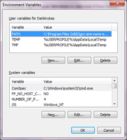
Select Advanced system settings then Environment variables...
-
Create PATH variable under User variables if it does not exist.
-
If PATH variable already exists, press Edit... button and add paths to msys tools, MinGW 4.9.2 tools and GCC ARM Embeded tools (for example "C:\msys\1.0\bin" for msys, "C:\Qt5.5.0\Tools\mingw492_32\bin" for MinGW 4.9.2 and "C:\Program Files (x86)\gcc-arm-none-eabi-4_9-2015q2\bin" for GCC ARM Embeded).
-
Press OK (3 times).
-
- Download EvvGC-PLUS source code from github. Extract .zip archive.
- Download QCustomPlot. Extract it. Copy qcustomplot.h and qcustomplot.cpp files to "Full-Path-to-EvvGC-PLUS-source/Configurator/3rdparty/".
- To build EvvGC-PLUS Configurator search for EvvGCPConf32.pro file in Configurator's source directory. Double click the file. If Qt 5.5.0 was installed correctly EvvGCPConf32.pro will be opened by Qt Creator. Click Configure Project. Click Run. Wait... Enjoy !
- To build EvvGC-PLUS firmware open command prompt window: press Windows+R. Type cmd. Press Enter. Browse to the location of EvvGC-PLUS firmware using cd command (for example cd Full-Path-to-EvvGC-PLUS-source/Firmware/evvgc-plus/). Type mingw32-make. Press Enter. Wait... Enjoy !
Here is the list the firmware was tested with by the original author:
-
Old version of EvvGC v1.2 board with IRF7343 FETs and manually installed pull-down resistors. The board was completely dead. Refurbished by me. This is donated hardware.


-
EvvGC v1.2 board with SI4599 FETs and pull-down resistors installed + IMU. The board was completely dead. Refurbished by me. This is donated hardware.


-
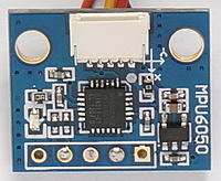
EvvGC v1.3 board + tiny IMU:


To increase motor driving efficiency EvvGC-PLUS firmware uses third harmonic injection (THI) technique. Using this technique, efficiency is increased by ~14%. The following graph shows waveform difference between simple sine wave based PWM and PWM with third harmonic injection applied:
!
(Waveform of simple sine wave based PWM versus Third Harmonic Injection (THI) PWM.)
To enable third harmonic injection PWM, check THI checkbox for selected output channel:

To stabilize the camera EvvGC-PLUS unlike original EvvGC firmware uses PID controller based on motor speed. Let us define the following variables:
- SP - set-point variable;
- PV - process variable;
- Err - process error;
- dT - time step between two consecutive iterations;
- P, I and D - proportional, integral and derivative coefficients of PID controller.
Set-point variable SP is desired position of the camera. Process variable PV is actual or measured position of the camera. Difference between SP and PV is process error Err or distance for motor to travel. Err = SP - PV
'''To be continued... '''